HiDes 2025 - 2026 microwave news
 |
| Calvin , as a visitor Darko OE7DBH , Jeff Taiwan 2026´ from L to R |
Small company passage.....
Hides 2025 microwave news - New products for the:
1.2 2.4 3.5 5.6 10 and 24 GHz bands
♠♠♠♠♠♠ Multiband FM TV Transmitter ♠♠♠♠♠♠
Project under development ( hopefully completed by the HamRadio time 2027 Friedrichshafen )
Target features:
■ 7 amateur radio bands from 900 MHz to 24 GHz , PLL locked.
■ Output RF power between 10 mW and 60 mW depending on the band.
■ Signal bandwidth compatible with IC-905 receiver BW 15MHz.
■ For NTSC and PAL modes.
■ Call sign display option selectable.
■ HDMI or CVBS input selectable.
■ Video polarity selectable ( positive or negative )
■ Two audio carriers ( switchable ) Mono !
■ Simultaneous transmission on any number of bands - possible !!
■ Separate potential-free contact ( 500mA ) for PA control for each band
■ Operating voltage: 10–14 V
■ Fully calibrated modular technology for self-installation in an enclosure, consisting of two modules: Control and TX board.
The control unit hardware is already finished , the first hardware prototype is complete.
Schematic, software and PCB Layout by DL1MFK.


Frequency Band TX switch :
Switch , screw-on version,
without retaining bolts.
Project description is still being prepared.....
♠♠♠♠♠♠♠♠♠♠♠ 2.4GHz Amplifier ♠♠♠♠♠♠♠♠♠♠♠


PA Nr.2 Maximum gain on: 2518 MHz
Bandwidth -1.5dB : 2382MHz......2587MHz
Bandwidth -3dB : 2268MHz......2716MHz
Bandwidth -6dB : 2144MHz......2851MHz
Typical gain and output power in CWmode....


Behavior of the amplifier with DVB signals.....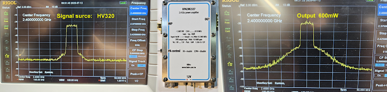


Here's a new version with different RF semiconductors.....

Maximum gain on: 2250 MHz
Bandwidth -3dB : 2130MHz......2375MHz
Bandwidth -6dB : 1806MHz......2598MHz
Typ. Gain sweep & 1W output.....

If you are interested in one or more PAs, please contact Calvin : calvin@hides.com.tw
♠♠♠♠♠ HPA2W1011 10 GHz power amplifier ♠♠♠♠♠♠

Measured data from a power amplifier on 10386 MHz CWmode , other test objects have similar data....
RF input PA gain dB RF output RFmon. V Ptot
4mW 27,8 2,37 W -1,77
3mW 28,8 2,30 W -1,75 12W
2mW 30,0 1,90 W -1,57 10,3W
1,5mW 30,4 1,63 W -1,43 9,4W
1mW 31,0 1,26 W -1,18 8,5W
0,7mW 31,5 0,97 W -0,97 8W
0,5mW 31,5 0,71 W -0,76 7,7W
0,3mW 31,7 0,45 W -0,51 7,6W
0,2mW 31,6 0,29 W -0,33 7,6W
Max. RF input power : 20mW ( You'll break it with 250mW )
Bandwidth: very wide , from under 9GHz to over 13GHz. ( if your pilot signal is not clean, then you need a bandpass filter before the amplifier ! )
Size: 47 x 87 x 17 mm aluminum housing ( without connector )
Operating voltage : 8.....15 Volt Typ. 12V Electricity consumption : max. 1 Amper
Optional Vcc : 5.8V ( max. 6.1V ) Consumption: max. 2A


The inner workings of an amplifier......

such as good RF substrate ROGERS material , good ground connections between top and bottom layer ,
hundreds of vias - almost invisible to the naked eye , good low-loss connection to the SMA connector ,
good rapid heat dissipation , etc.


Source: https://www.ebay.com/itm/327007110669?itmmeta=01KHR2EVMH62TRY1YFDRRCQPWW&hash=item4c2324860d:g:l8wAAeSwUxNplYBS
 The same applies to multipliers with power amplifiers !!!


Regardless of the input video level between 0.2Vpp and 2Vpp , the output will always be the standardized 1Vpp
about: 382euro
The operating voltage is 8V to 15V , but the module can also be operated with 6V ( tolerance range 5,9V.....6,0V )
What needs to be done then ? ....For technicians only !!
Optional: operating voltage 6V
1. remove R2

2. connect....

♠♠♠♠♠♠ Multiplier with 10GHz Power Amplifier ♠♠♠♠♠♠

This is 98% the same design and circuit diagram , only one additional Hittite multiplier IC has been added.
The inner workings.....

There are two versions.....
1. Input 1200......1320MHz ( x8 ) -20dBm ..... 3mW 50ohm
2. Input 2460.....2630MHz ( x4 ) -20dBm ..... 3mW 50ohm
No matter what power you give to input ( -20dBm..... +5dBm ) , at 10GHz the output is always over 2W
Output: 9,60 GHz ....... 10,56 GHz > 2.0 Watt output power in CW mode & 50ohm
"Conversion gain" : >50dB
Monitor RF pin: negative , -1.75V & 2.37 Watt RF output
Vcc & Icc : 8.......15 Volt 1 Amper & 12V ( optional Vcc: 6V )
Use purpose: 10GHz signal source, beacon transmitter, CW transmitter, FM transmitter, FMTV transmitter, etc.
Source: https://www.ebay.com/itm/227221921308?itmmeta=01KHR2EVMHGXQSKFV3N3W9EA18&hash=item34e77b5e1c:g:LqAAAeSwBAhplYk3

Article in progress.......
♠♠♠♠♠♠♠♠ Video level adjuster and 3-way distributor ♠♠♠♠♠♠♠♠
VR-100 1Vpp video level regulator with Matsushita-Panasonic AN302 Chip ( or replacement type NTE1264 , ECG1264 , SPD1264 )
The previously published circuit ( DC9MD ) does not fully meet the requirements for transmission. Active clamping of
the video signal is essential for stable transmission , a triple output free of reflection , finally allows the connection
of a preview monitor and a control output for a wave monitor.
This circuit can also be used in the receive path, for example, to amplify the video signal from a commercial
satellite receiver that is currently receiving a signal from the IC-905 transmitter.


Manual fine-tuning is also possible between 0.85Vpp and 1.15Vpp using P1 trimer.
The response time is approximately 0.4 seconds. Low-noise transistors ensure professional data,
The response time is approximately 0.4 seconds. Low-noise transistors ensure professional data,
therefore no impact on image quality.


IN-OUT : 75 ohm
IN : 0,2V.........3V
OUT : 1Vpp
Bandwidth: 10Hz........8MHz Enhanced video frequency range: 2,8MHz......4,8MHz
Vcc : 10.....12V
Icc : 110mA
PCB size : 55 x 35mm
Available in three options:
1. Assembled PCB without AN302 € 40.-
2. Assembled and calibrated PCB with AN302 € 65.-
3. Pre-installed in the housing, ready to use € 95.-
The sale starts at HamRadio 2026 in Friedrichshafen in the flea market hall at the HiDes stand.


Article in progress........
Please also check out other posts, the link continues below.
↓


Kommentare
Kommentar veröffentlichen